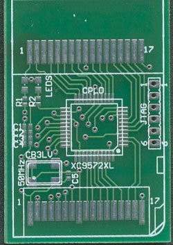
Original PCB
Original PCB
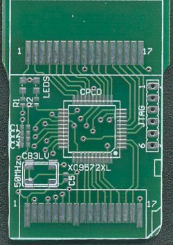
Ground PCB
Liberally apply flux to all 44 pads. Lay CPLD on pads and make sure they all line up with the dot on the CPLD in the same position as the dot on the PCB.
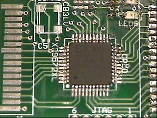
CPLD
When you are complete, now we test each pin on the CPLD to make sure we have a connection from the CPLD to the PCB. So, set your multimeter to test for shorts or diodes. Then, put one lead on pin 1 of the CPLD and the other lead on the farthest part of the pad that it touches. This will confirm that your CPLD is connected. Do that for each pin.
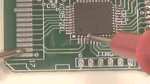
Testing Pin 3 on CPLD
Now, when soldering the PCI Pins on, I would solder two or three, and then test fit the cart, to make sure everything is lining up fine. After soldering all the PCI pins on, I would test from the cart to the PCB connection to make sure the pins were making contact with the cart. If not, remove the cart and gently press down on the pin(s) to bend them down.
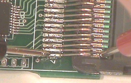
Testing Cart to PCB
Finish your PassMe by applying a 1" x 3" sticker, or tape to the back of the PCB. This will keep the bottom contacts from shorting out inside the DS and causing damage.
For those of us that would like to express ourself, and go beyond the bare minimum can add flair by putting on the 2 LEDs and 2 Resistors. Now, keep in mind that THESE ARE NOT NEEDED! And, I will tell you right now. Get ready for some frustration. The resistors are MICRO sized. Like the width of a hair! And I don't mean a rabbit. They have no problem sticking to just about EVERYTHING but the PCB after they have touched the flux.
Anyway, add flux to the pads on the PCB. Now, place the resitor on the PCB between the pads labeled R1. Try to hold the resistor down in place and quickly touch the end with the soldering iron. Now, continue holding the resistor in place and quickly touch the other side as well. Repeat for R2.
The LEDs are a little "harder", and if you touch them for to long, the pads will melt off. That would be bad (and believe me, I know). I found it easier to have the LEDs a little to the sides when soldering as the pads on the PCB and the LEDs are the exact same distance. And unless you can solder UNDER the LED, it's a little difficult to solder.
Now, on to jtag Construction.
 1.3.9.1